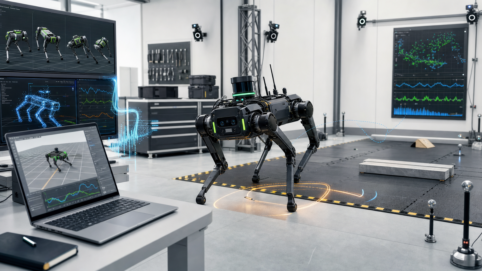
A small difference between simulation and reality can turn into a major failure the moment a policy is placed on a real body.
A robot that walks well in simulation may suddenly shake and fall when it enters the real world.
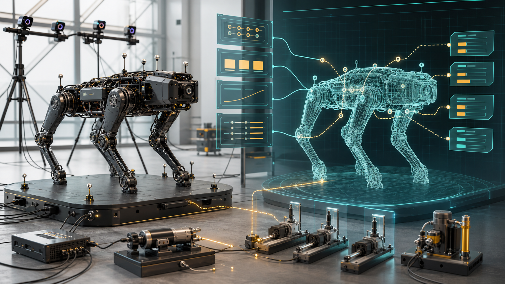
Inside the computer, a policy may climb stairs, run quickly, and keep its balance. But the moment it is placed on an actual robot, it can stop behaving as expected. Here, a policy is essentially a function that receives the robot's state and decides the next action.
When people see this kind of problem, they usually think first about better learning algorithms: a more robust policy, a larger neural network, more domain randomization, or a more sophisticated simulator. All of those matter. But in my view, many sim-to-real failures begin somewhere much more basic.
The simulation is not describing the real robot accurately enough.
Robots are strongly constrained by the physics of the real world. Actuators have limits on the torque and speed they can produce. Sensor data has latency. Reducers have backlash. These differences may look small, but the more dynamic the policy becomes, the more serious they become.
The sim-to-real gap sounds like a grand research slogan, but in practice it is closer to the sum of modeling errors.
When training a controller with reinforcement learning, we cannot collect data by letting a real robot fall and break thousands of times. So we model the robot inside a simulation as close to reality as possible, train a policy there, and then transfer it to the real world.
The problem is that "modeling something close to reality" is harder than it sounds.
When people talk about sim-to-real, they often point to things that are fundamentally difficult to model, such as friction or deformable objects. Those are difficult, of course. But even before reaching them, much more basic things are often missing: the true operating limits of the actuator, an inaccurate URDF, sensor latency, and reducer backlash.
These are not mysterious unsolved physics. They are things you can measure, put into the model, and verify. Yet they are surprisingly often left out. I do not put much faith in the phrase "learning will handle it." A learning framework only optimizes inside the world it is given. If that world lies, the policy will learn to exploit the lie.
A motor's limits are not a rectangle

Motor limits are better understood as a complex operating region than as a simple rectangle made from maximum torque and maximum speed.
The first thing often missed is the MOR, or motor operating region. Put simply, it describes how much torque a motor can produce at a given rotational speed.
When putting a robot into simulation, people commonly use a format such as URDF. It contains physical parameters such as link length, joints, mass, inertia, and joint limits. But in many cases, the actuator itself is modeled too simply.
URDF has fields for maximum torque and maximum angular velocity. That makes it easy to assume that any command inside that rectangular region is possible. But the limits of a real actuator are not shaped that simply.
Especially in dynamically moving robots, the actuator often operates near the boundary of its MOR to produce large output. If the motor limit is modeled as a simple torque-speed rectangle, the policy learns while believing it can use force that does not exist in reality.
If the simulation says, "You can still produce high torque at this speed," the policy will use it. But if the real motor can barely produce torque at that speed, the expected state transition will not happen on the real robot. The posture shifts, the next observation shifts, and eventually the whole motion collapses.
That is why the simulation needs a properly shaped MOR rather than a rectangle.
Without it, the policy is trained from the beginning against a motor that does not exist.
Real robots do not see ground truth
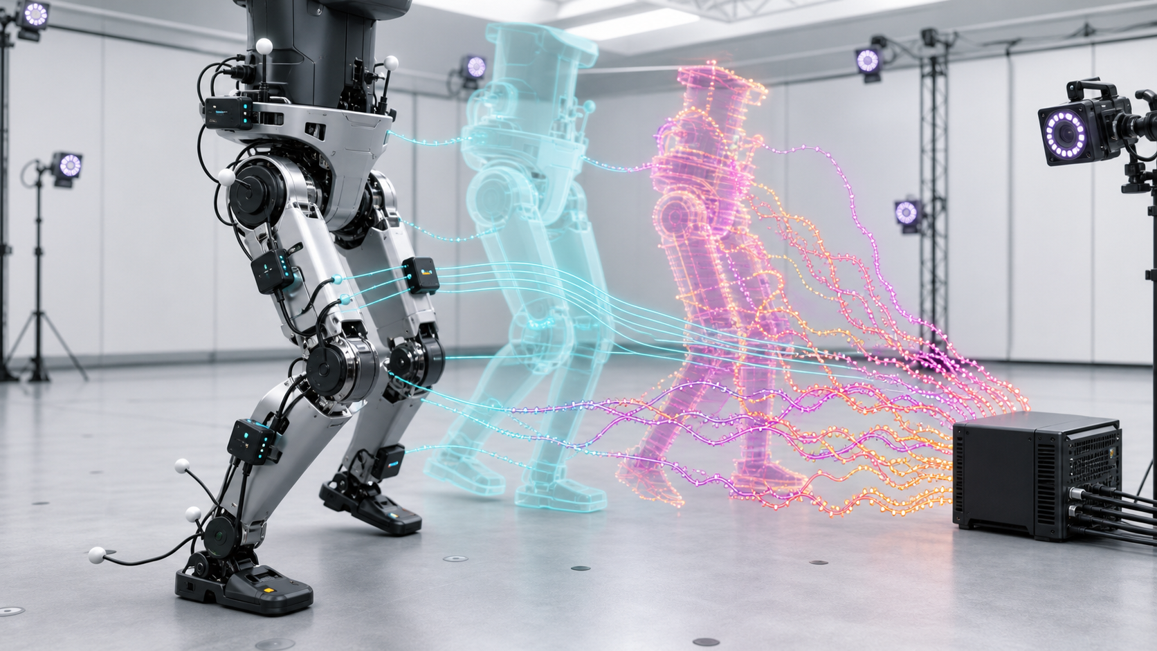
Between simulator ground truth and real sensor or estimator output, noise and delay inevitably enter the loop.
The second problem is observation.
Inside a simulation, every value can be known exactly. The simulator has ground truth for how much the body is tilted, whether the foot is touching the ground, and what the joint angles and velocities are. So it is easy to feed those values directly into the actor. Here, the actor is the execution part of the policy that receives observations and produces actions.
But a real robot cannot see ground truth.
Some values, such as joint angles, can be read directly. But body orientation and foot contact usually have to be estimated. Orientation may be estimated through an IMU and a filter. Contact may be judged through a force sensor or a kinematics-torque-based estimator.
The problem is that these values are not clean. Real sensors arrive late, jump, and are polluted by impacts or vibration. If a value exceeds the sensor range, it may saturate. A filter uses past information to estimate the current state, so it structurally introduces delay.
In simulation, the policy was trained on clean truth. In reality, delayed and noisy estimator output enters as the observation. From the policy's point of view, it is seeing a different world from the one it learned.
When observation is corrupted, action is corrupted too. When action becomes strange, the robot's state gets worse, and that worse state produces even stranger observations. A small error can travel through a positive feedback loop and become motion failure.
So it is not enough to add sensor noise to the simulation by feel. We need to check which values arrive with which delays on the real robot, how far estimator output is from ground truth, and what errors appear under impact or vibration. If possible, we should use external cameras or markers to measure something close to true state, then compare that with the robot's internal estimator output.
It is tedious, but if this step is skipped, the real robot keeps moving while believing in the wrong body state.
If the URDF is wrong, the policy trained on another body
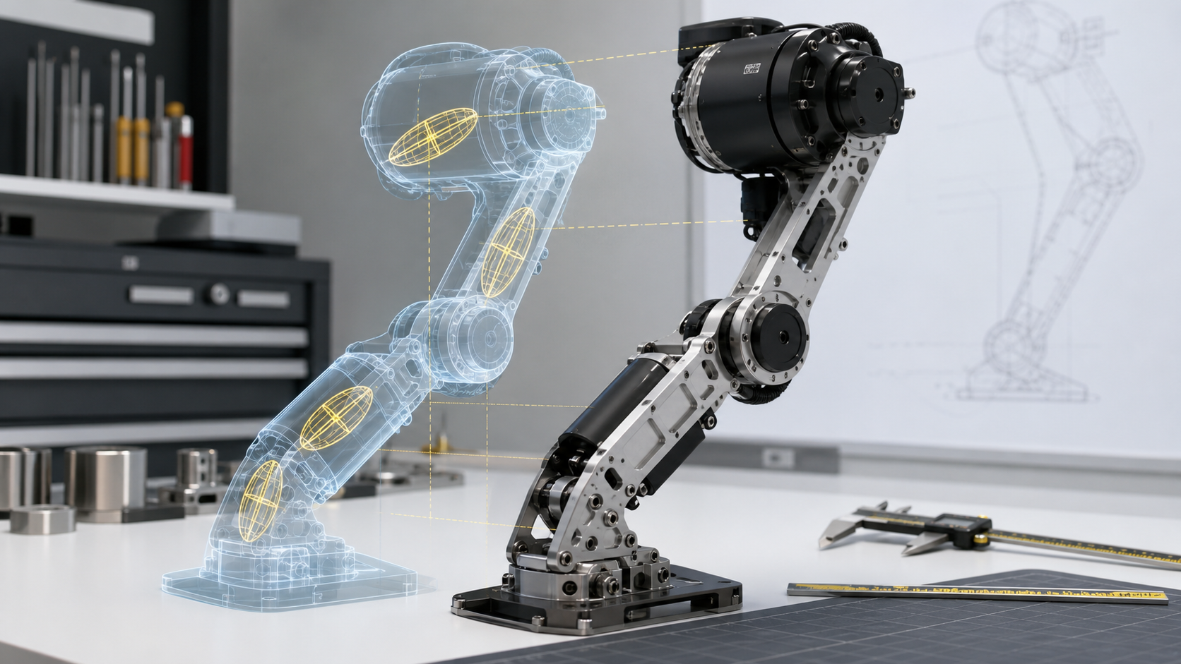
When the URDF and the real hardware disagree on mass, inertia, or assembly details, the policy has effectively trained on a different body.
The third problem is the URDF.
A URDF is like a blueprint of the robot. It includes information such as link length, joint axes, mass, and inertia. The control side trusts this file when building the simulation.
The issue is that the file can be wrong.
If a length or joint position is wrong, it is relatively visible. Mass can also be checked to some degree with a scale. But the inertia matrix is different. Measuring the inertia matrix of a single link in 3D space requires more complicated equipment than a scale and a ruler.
Usually, the CAD model is made as close to the physical part as possible, and inertia properties are extracted from it. For that to work, dimensions, material, mass, and internal structure all need to match reality. But parts may differ from the design during manufacturing, wiring and fasteners may be missing from the model, or a URDF received from another lab or company may not match the actual hardware.
Then the policy trains against the wrong body. If the real robot's inertia differs, the same torque produces different acceleration, and the same motion produces a different response. In dynamic motion, that immediately becomes a sim-to-real gap.
The worse part is that debugging is hard. When a robot moves strangely, it is difficult to say right away, "This link's inertia matrix is wrong." Eventually you have to disassemble the robot, measure masses, compare them with CAD, and align simulation values with reality one by one.
This is a technical problem, but it is also a trust problem between hardware and software. If an inaccurate hardware model is handed over, the software side optimizes diligently inside the wrong world.
Latency and backlash amplify small tremors
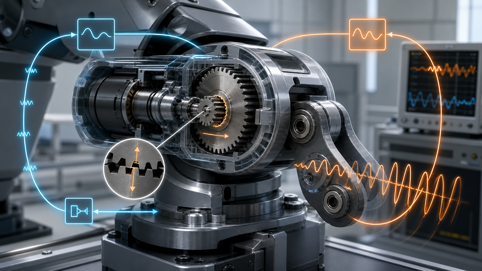
Backlash and latency can turn small errors into oscillations inside a feedback loop.
The final issues are latency and backlash.
Real sensors and actuators do not react instantly. Encoders, IMUs, and cameras each have different readout rates and different latencies. A motor command also does not become torque the instant it is computed; it passes through the current loop and driver before appearing as real force.
In simulation, it is easy to treat every value as arriving immediately and every command as being reflected immediately. But in reality, some values arrive late, and some commands take time to appear.
On the actuator side, there is also backlash. Backlash is the small gap between gears. Within that gap, the motor rotor may move while the external link has not yet followed. Then the motor can behave as if it is seeing only the much smaller rotor inertia rather than the full link inertia.
At that moment, the motor accelerates faster than expected. The controller sees this and sends torque in the opposite direction, but that response also arrives late through latency. As this repeats, small gaps and small delays can act like positive feedback and grow into vibration.
When a robot trembles as soon as it turns on, or suddenly becomes unstable during a particular motion, small delays, compliance, and backlash are often acting together.
Backlash is difficult to remove completely. If so, the simulation should at least include latency, reflect actuator dynamics, and train the policy to be insensitive to this kind of noise.
The sim-to-real gap has a very physical face.
Why don't people just do the obvious things?
At this point, an obvious question appears.
Why not just do it? To draw a good MOR, measure the motor's resistance, inductance, and torque constant. Validate the estimator. Build the URDF properly. Measure latency and backlash.
That is right. But people often do not.
The reason is practical. For many researchers, sim-to-real itself is not the real topic. The core of the paper is often a new learning algorithm, simulator, or policy architecture. In that case, the robot experiment serves as evidence that the proposed method can be applied to a real robot.
So the author does not want to spend months solving sim-to-real. If simulation shows 100 percent performance and the real robot shows 30 percent, but that is enough to finish the paper, the paper-per-time ratio looks much better.
Reality often moves in the opposite direction. Skipping the basic modeling and putting the policy directly onto the robot may feel like it could save time, but that kind of luck is rare. Experiments almost never work on the first try, so more time is spent debugging failures.
By contrast, measuring and aligning things one by one is certainly slow, but once the model is aligned, it transfers to reality with much higher performance.
Calibration is the repeated work of matching real measurements back to the simulation model.
This is where robot calibration becomes important. It is the work of measuring a real robot, building an actuator model, validating the URDF and inertia, checking sensor and estimator delay, and producing a simulation model that can be used directly for learning.
For teams building custom hardware in particular, this process becomes a major bottleneck. A robot built in-house does not have an already validated model, and the agreement between hardware and software keeps changing. If measurement and model fitting can be done systematically, trial and error can be reduced significantly.
Whether this becomes a meaningful market depends on the direction of the robotics industry. If everything converges into a few general robot platforms, the opportunity may be limited. If task-specific robots and custom hardware keep increasing, this could become a very important bottleneck.
Writing reality honestly is the next bottleneck
Sim-to-real is not a problem that ends with "a better neural network will solve it."
Robots live in the physical world. Motors are limited by voltage and heat. Sensors arrive late. Gears have backlash. Link inertia may differ from CAD. No matter how good a policy is, if the world it learned and the real body differ, it will break in reality.
Good sim-to-real is therefore a surprisingly humble task. Measure what the robot can produce, check what it can sense, observe which values arrive late, and find which parameters are wrong. Then put those differences into the simulation or make the policy robust to them.
This work is not as flashy as a demo video. But if a real robot is going to walk, run, climb stairs, and avoid falling, it eventually returns here.
The sim-to-real gap is not an abstract research slogan. It is a question of how accurately hardware and software make promises to each other.
The reasons a robot does not obey in reality are usually not grand. A boxed motor limit, an unvalidated estimator, wrong inertia, ignored latency and backlash. These pile up and separate the world the policy learned from the world it actually enters.
For now, the most reliable way to reduce that gap is simple.
Model reality more honestly.